Rendering Pipeline
A scratch-built 3D rendering pipeline built with C++ and SDL.
By Jonathan Lee.
May 13, 2023
For my Computer Graphics II course, we each had to build a 3D rendering pipeline from scratch using any programming language of our choice and primitive display APIs. I implemented mine in C++ because I wanted to get more familiar with C++ as it is widely used in the robotics industry. Simple DirectMedia Layer (SDL2) provides an interface to create a window and set pixel values to be drawn to the display.
The renderer was implemented in four stages:
- Perspective Vector Display System
- Rasterization and Z Buffer
- Shading and Illumination
- Texture Mapping
Sections
- 1 - Perspective Vector Display System
- 2 - Rasterization and Z Buffer
- 3 - Shading and Illumination
- 4 - Texture Mapping
- 5 - References
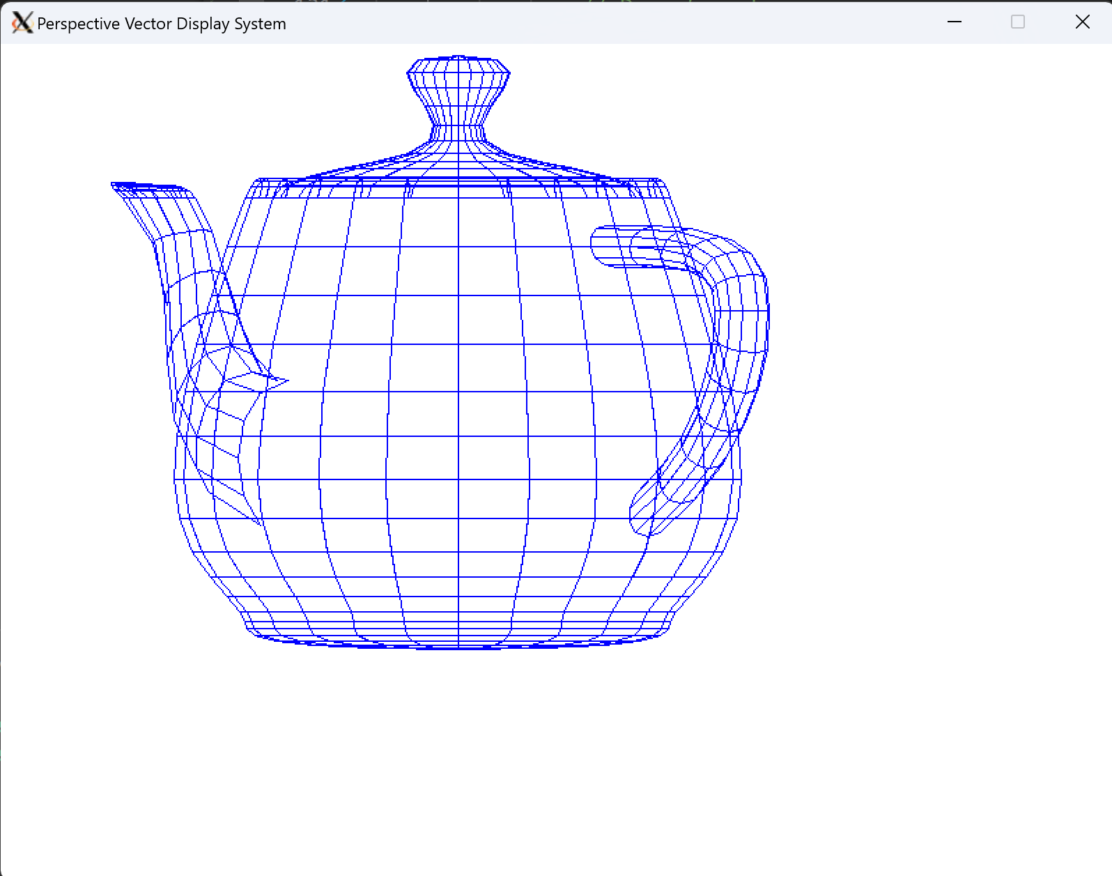
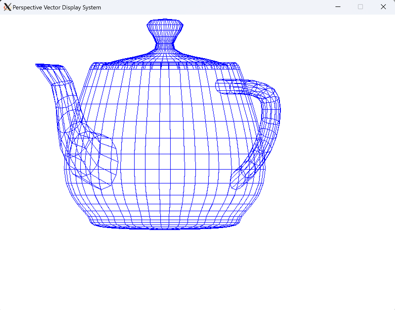
1 - Perspective Vector Display System
The first step is to display the perspective view of an object with back faces removed. The geometric data for a polygonal object is specified in a “.d” file format and vertices and edges are read by the program.
Since C++ does not have any standard library for vector and matrix math, I had to implement several utility classes along with a camera and model class.
Class vec3 {      // vec3.h
    vec3(float x, float y, float z);
    dot(vec3 v);
    cross(vec3 v);
    normalize();
    ...
}
Class vec4 {...}  // vec4.h
Class mat4 {...}  // mat4.h
Class Camera {  // camera.h
    Camera();
    mat4 GetViewMatrix();
    mat4 GetPerspectiveMatrix();
}

Class Model {   // model.h
    LoadModel(const char* path);
    DrawEdges(Camera camera, SDL_Renderer *renderer);
    ResizeModel();
    CalcBound(vec3 min, vec3 max);
    Scale(float scale);
    Translate(vec3 offset);
    Rotate(float x, float y, float z);
}
The DrawEdges() method calculates what the edges of the model would look like in device coordinates by applying the perspective transformation. It also reduces computation by not drawing faces that are back facing.
void Model::DrawEdges(Camera &camera, SDL_Renderer *renderer) {
    // Calculate transformation matrix
    mat4 model_matrix = translate_matrix * rotate_matrix * scale_matrix;
    mat4 view_matrix = camera.GetViewMatrix();
    mat4 perspective_matrix = camera.GetPerspectiveMatrix();
    mat4 model_view_matrix = perspective_matrix * view_matrix * model_matrix;

	  // For each face in the model
    for (unsigned int i = 0; i < faces.size(); i++) {
        // For each edge
        for (unsigned int k = 0; k < faces[i].indices.size(); k++) {
            int p0 = faces[i].indices[k];
            int p1 = faces[i].indices[(k + 1) % faces[i].indices.size()];

            // Apply model_view_matrix
            vec4 h0 = model_view_matrix * vec4(verts[p0], 1.0f);
            vec4 h1 = model_view_matrix * vec4(verts[p1], 1.0f);

            // Check if the face normal is not backfacing
            vec4 n4 = model_view_matrix * vec4(face_normals[i], 1.0f);
            vec3 normal = vec3(n4.x, n4.y, n4.z).normalize();
            if (normal.z < 0) {            {
                // Render the line

                // Scale normalized coordinates to device coordinates
                float x1 = 200.0*h0.x+400;
                float x2 = 200.0*h1.x+400;
                float y1 = 200.0*h0.y+600;
                float y2 = 200.0*h1.y+600;
                // flip y axis
                y1 = 600 - y1;
                y2 = 600 - y2;
                SDL_RenderDrawLine(renderer,x1,y1,x2,y2);
            }
        }
    }
}
Results:
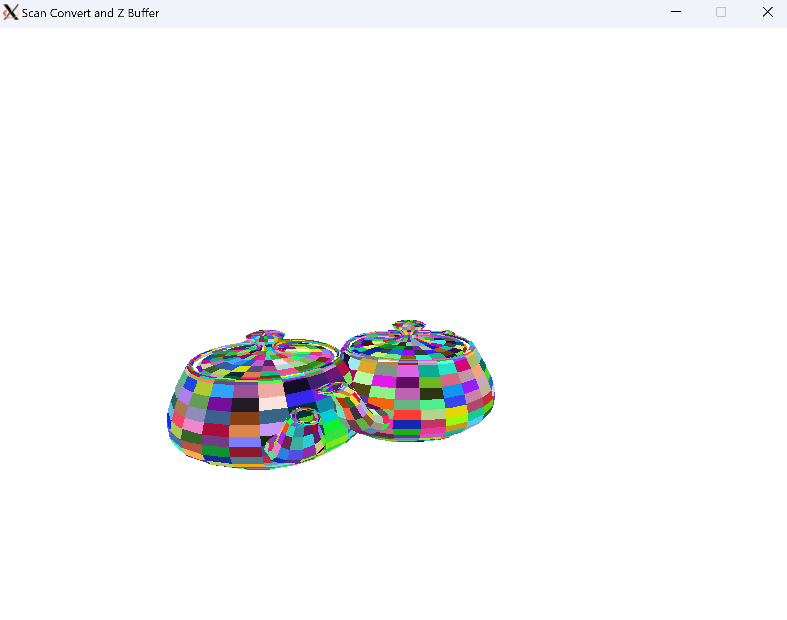
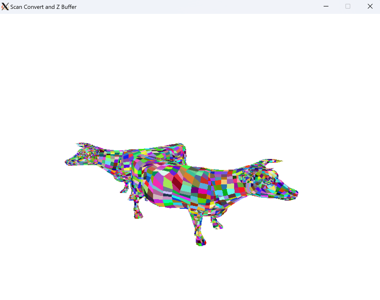
2 - Rasterization and Z Buffer
Now, instead of drawing a wireframe, we want to color the model. This step is rasterization where the color of each pixel in the screen is determined. I implemented the scan conversion algorithm, which fills in the pixels of each polygon to the screen. Then a z buffer is used to keep a depth map of each pixel, that way the correct pixel is drawn for overlapping polygons.
2.1 - Scan Conversion
The Edge Table and Active Edge Table are implemented in utils/edgetable.cpp. The Edge Table is implemented as a hash table of edges using the std::map template. The keys are the scanlines, which each contain a linked list of edges sorted on the x intercept of the lowest point.
class Edge {
public:
    int y_max;      // scanline of high edge
    float x_min;    // x value at low edge
    float inv_m;    // 1/m slope
    float z_min;    // z value at low edge
    float del_z;    // rate of change from z_min
    Edge *next;     // next edge in EdgeTable bucket
}
During the DrawFaces() function in utils/model.cpp, the Edge Table is populated with the edges of the face. Then as scanlines are iterated over, edges are moved from the Edge Table to the Active Edge Table. This utilizes the std::multimap, which allows for duplicate keys, since each edge is keyed on its x_intercept, which can have duplicates. The Active Edge Table is updated after each scanline.
Here is part of the scan conversion process.
ActiveEdgeTable aet;

// Iterate over scanlines
// Stop when ET and AET are empty
for (int y = et.scanlines.begin()->first; (!et.IsEmpty() || !aet.IsEmpty()) && y < SCREEN_HEIGHT; y++) {
    // Move edges from ET to AET
    Edge* e;
    while((e = et.RemoveEdge(y)) != nullptr) {
        // AET is keyed by x_int
        int x_int = (int)round(e->x_min);
        aet.InsertEdge(x_int, e);
    }

    // Draw lines between pairs of edges in AET
    std::multimap<int,Edge*>::iterator it;
    for (it = (*aet.aet).begin(); it != (*aet.aet).end(); it++) {
        int ix0 = it->first;
        Edge *e0 = it->second;
        it++;
        int ix1 = it->first;
        Edge *e1 = it->second;

        // Fill in points between and including edges
        float z0 = e0->z_min;
        float z1 = e1->z_min;
        float hor_del_z = (z1 - z0)/(ix1 - ix0);
        float z = z0;

        for (int x = ix0; x <= ix1; x++) {
            // Only draw point if point is in front of current z value
            if (comparefloats(z,z_buffer[x][y][3], FLOAT_TOL) == -1) {
                z_buffer[x][y][3] = z;

                SDL_RenderDrawPoint(renderer, x, y);
            }
            z += hor_del_z;
        }
    }
    // Update edges
    aet.UpdateEdges(y);
}
2.2 - Z Buffer
The z value for each point is calculated by trilinear interpolation. Each edge stores a minimum z value and rate of change of that z value. The point is only drawn if its depth value is less than the current value in the z buffer. If it is in front, the point is drawn and the z buffer is updated.
// Fill in points between and including edges
float z0 = e0->z_min;
float z1 = e1->z_min;
float hor_del_z = (z1 - z0)/(ix1 - ix0);
float z = z0;

for (int x = ix0; x <= ix1; x++) {
	// Only draw point if point is in front of current z value
    if (comparefloats(z,z_buffer[x][y][3], FLOAT_TOL) == -1) {
    	z_buffer[x][y][3] = z;
        SDL_RenderDrawPoint(renderer, x, y);
    }
    z += hor_del_z;
}
Results:
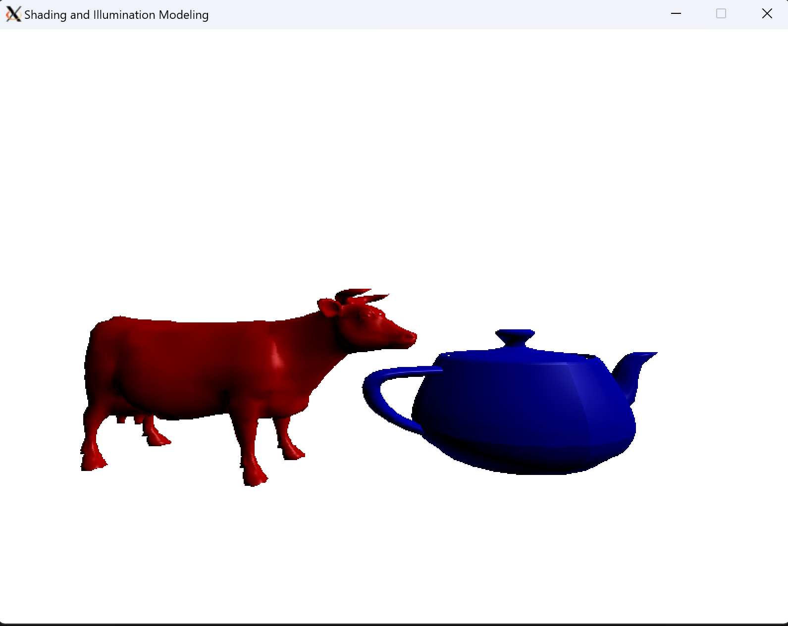
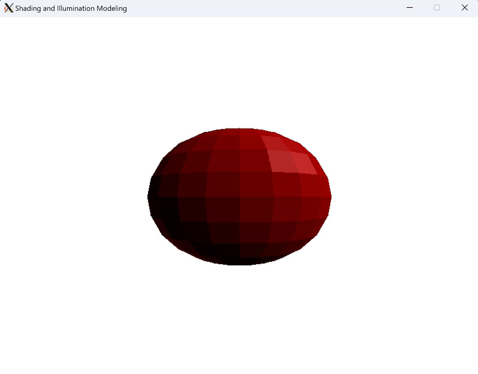
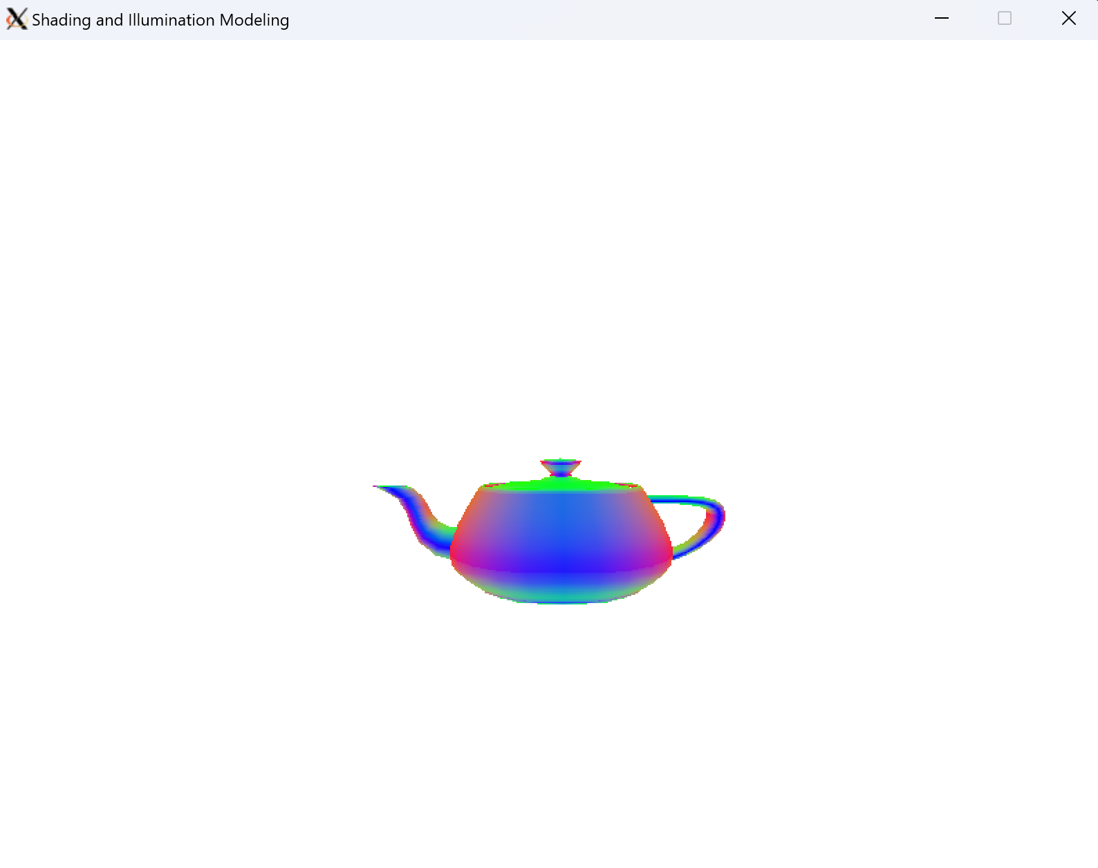
3 - Shading and Illumination
3.1 - Phong Illumination Model
First I implemented a Light and Material class in utils/illumination.cpp. The Light class contains information on the position, color, and direction of the light. The material class has different constants for color, ambient, diffuse, specular, and shininess components.
class Light {
    vec3 position;
    vec3 color;
}

class Material {
    vec3 color;
    float k_ambient;
    float k_diffuse;
    float k_specular;
    int shininess;
}
The illumination is calculated according to the Phong Illumination equation.
\[I = I_E+K_aI_ambient+K_d(N \cdot L)I_{light}+K_s(V \cdot R)^n I_{light}\]vec3 Material::PhongIllumination(vec3 view, vec3 normal, vec3 light_direction, Light light) {
// Assume V, N, L are normalized
vec3 V = view;
vec3 N = normal;
vec3 L = light_direction;
vec3 R = 2 * (N.dot(L)) * N - L;
vec3 i_ambient = this->k_ambient * this->color;
vec3 i_diffuse = this->k_diffuse * (N.dot(L)) * this->color;
vec3 i_specular = vec3();
if (V.dot(R) > 0)
i_specular = this->k_specular * pow(V.dot(R),this->shininess) * light.color;
return i_ambient + i_diffuse + i_specular;
}
The PhongIllumination() function returns a vector color intensity between 0 and 1 for each RGB channel. This is scaled to a pixel value between 0 and 255.
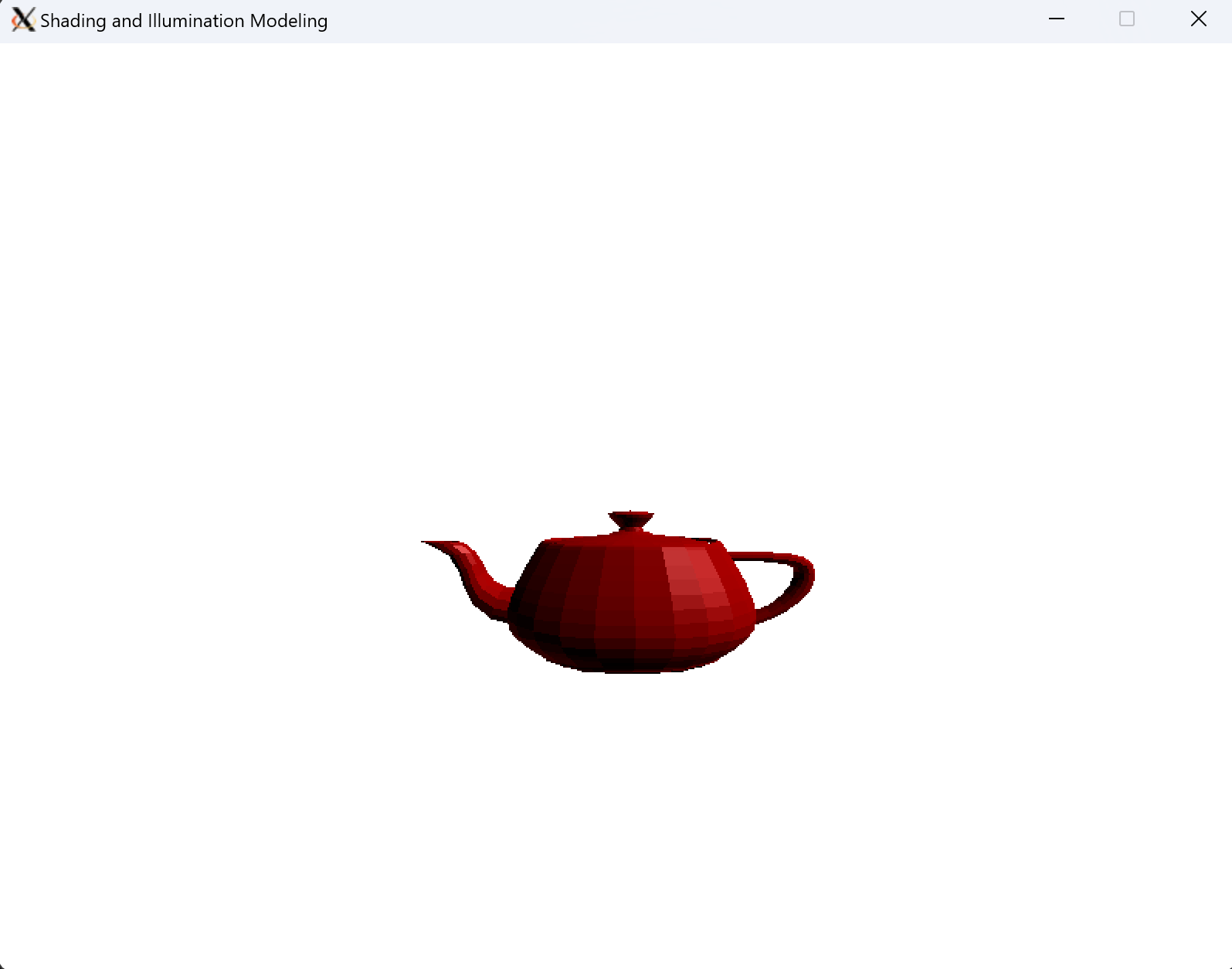
3.2 - Flat Shading
Flat shading is implemented in utils/model.cpp:DrawFlat(). Before each face is drawn, the face normal in the world space is calculated. The light and camera are assumed to be infinitely far away, and are constant for all faces. Then the Phong Illumination model is invoked to determine the intensity of that face. Each pixel is drawn with the same intensity in the scan conversion process.
/* DrawFlat() ... */
    // Calculate surface normal
    vec4 _v0 = model_matrix * vec4(verts[faces[i].indices[0]], 1.0);
    vec4 _v1 = model_matrix * vec4(verts[faces[i].indices[1]], 1.0);
    vec4 _v2 = model_matrix * vec4(verts[faces[i].indices[2]], 1.0);
    vec3 v0 = vec3(_v0.x, _v0.y, _v0.z);
    vec3 v1 = vec3(_v1.x, _v1.y, _v1.z);
    vec3 v2 = vec3(_v2.x, _v2.y, _v2.z);
    vec3 surface_normal = ((v0-v1).cross(v2-v1)).normalize();

    // Calculate intensity
    vec3 intensity = material.PhongIllumination(view_direction, surface_normal, light_direction, light);
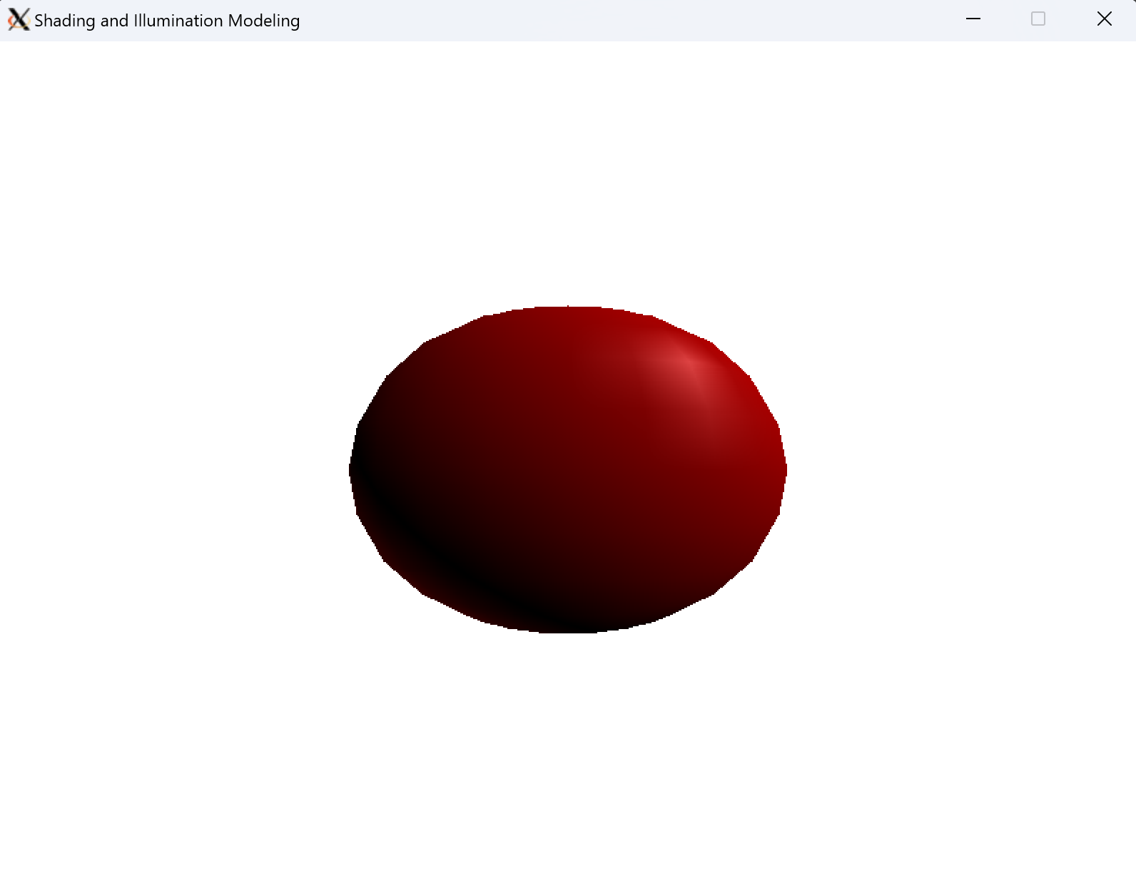
3.3 - Gouraud Shading
Gouraud shading is implemented in utils/model.cpp:DrawGouraud(). Prior to the scan conversion process, the face normals and vertex normals are calculated by averaging face normals. Then the Phong Illumination model is invoked on the vertex normals. In the scan conversion process, the intensity is tri-linearly interpolated to give the pixel value.
/* DrawGouraud() ... */
    // Calculate verts normals
    for (size_t i = 0; i < verts.size(); i++) {
        // Get all faces containing this vertex
        std::vector<int> faces_index;
        for (size_t j = 0; j < faces.size(); j++) {
            // Loop through all indices of the face to check if the vertex is in it
            for (size_t k = 0; k < faces[j].indices.size(); k++) {
                if ((unsigned int)faces[j].indices[k] == i) {
                    faces_index.push_back(j);
                }
            }
        }
        // Then average their normals
        vec3 normal_sum(0, 0, 0);
        for (size_t i = 0; i < faces_index.size(); i++) {
            normal_sum += face_normals[faces_index[i]];
        }
        vert_normals[i] = (normal_sum / faces_index.size()).normalize();

        // Calculate intensity
        vert_intensities[i] = material.PhongIllumination(view_direction, vert_normals[i], light_direction, light);
    }
3.4 - Phong Shading
Phong shading is implemented in utils/model.cpp:DrawPhong(). Prior to the scan conversion process, the face normals and vertex normals are calculated by averaging face normals. In the scan conversion process, the vertex normals are tri-linearly interpolated. Then the Phong Illumination model is invoked on each pixel.
/* DrawPhong() ... in the scan conversion process */
// Draw lines between pairs of edges in AET
    std::multimap<int,Edge*>::iterator it;
    for (it = (*aet.aet).begin(); it != (*aet.aet).end(); it++) {
        int ix0 = it->first;
        Edge *e0 = it->second;
        it++;
        int ix1 = it->first;
        Edge *e1 = it->second;

        // Fill in points between and including edges
        float z0 = e0->z_min;
        float z1 = e1->z_min;
        float hor_del_z = (z1 - z0)/(ix1 - ix0);
        float z = z0;

        // Interpolate vertex intensity horizontally
        vec3 start = e0->vec_min;
        vec3 end = e1->vec_min;
        vec3 hor_del_vec = (1.0/(ix1 - ix0))*(end - start);
        vec3 norm = start;

        for (int x = ix0; x <= ix1; x++) {
            // Only draw point if point is in front of current z value
            if (comparefloats(z, buffer[x][y][3], FLOAT_TOL) == -1) {
                buffer[x][y][3] = z;

                // Calculate intensity
                norm = norm.normalize();
                vec3 intensity = material.PhongIllumination(view_direction, norm, light_direction, light);

                Uint8 r = (Uint8)floor(abs(intensity.x) * 255.0);
                Uint8 g = (Uint8)floor(abs(intensity.y) * 255.0);
                Uint8 b = (Uint8)floor(abs(intensity.z) * 255.0);
                SDL_SetRenderDrawColor(renderer, r, g, b, 0xFF);
                SDL_RenderDrawPoint(renderer, x, y);
            }
            z += hor_del_z;
            norm = norm + hor_del_vec;
        }
    }
3.4 Comparison of Shading Techniques


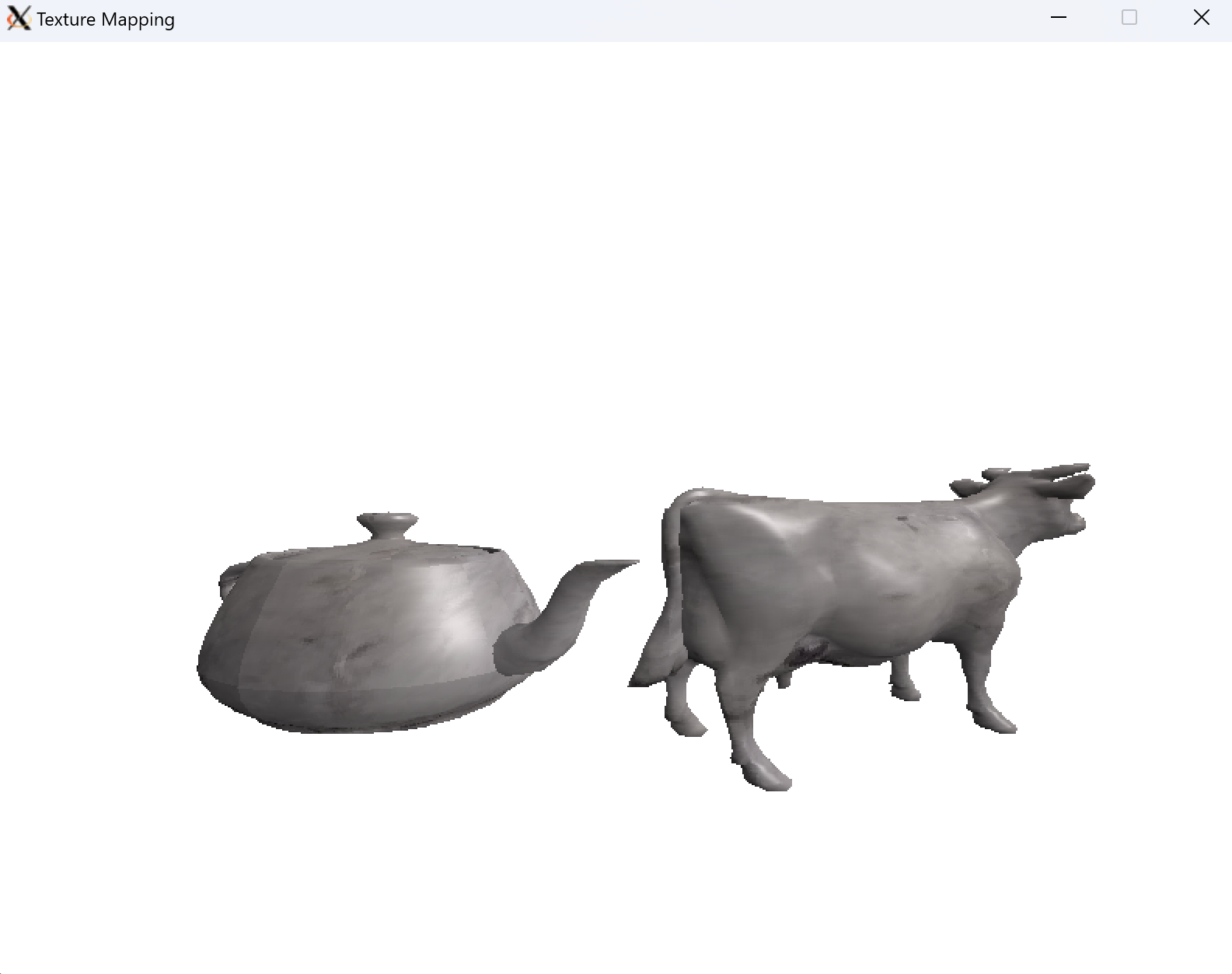
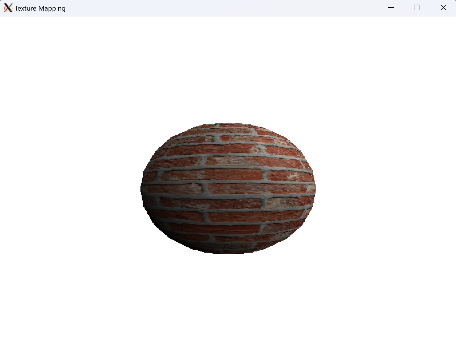
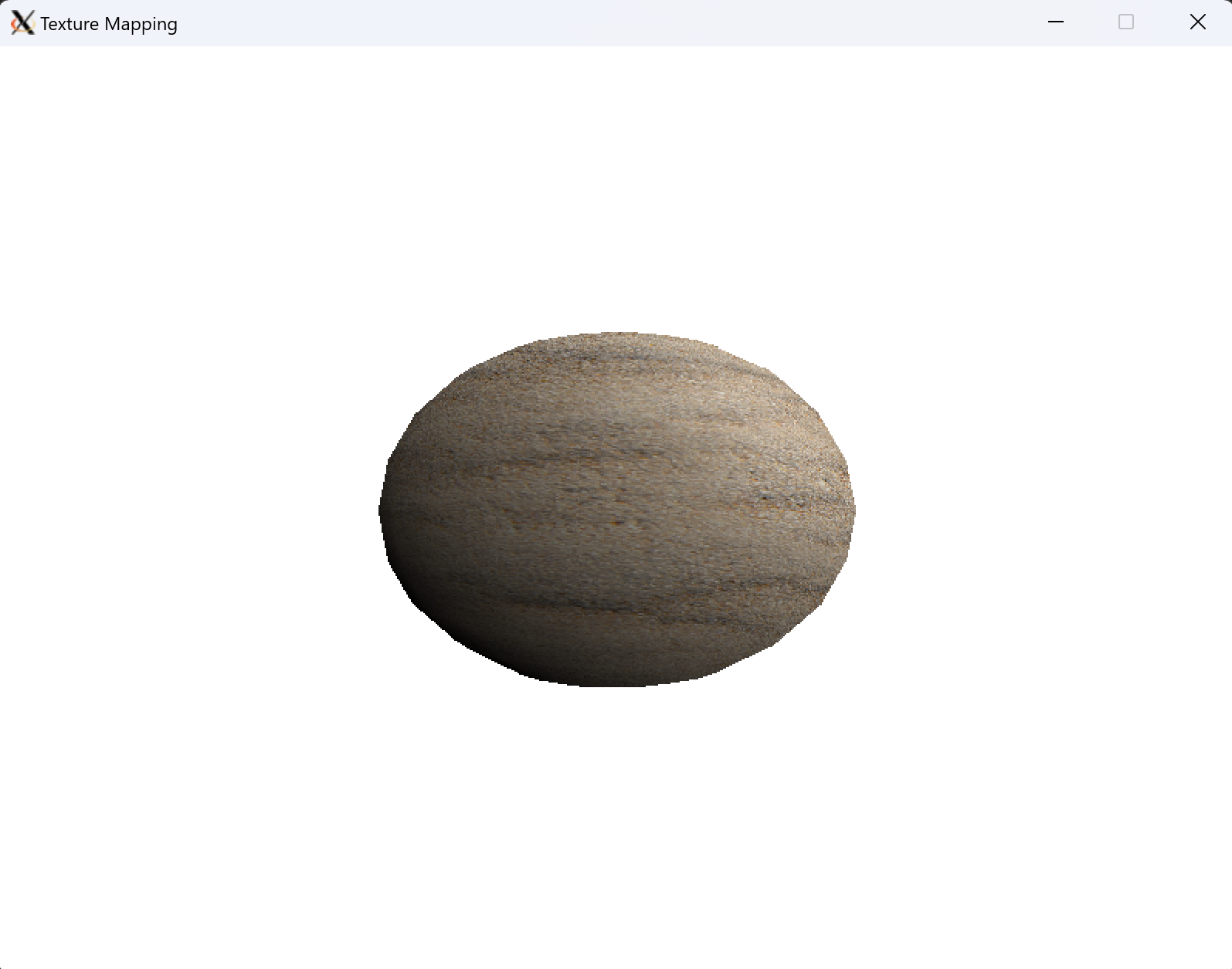
4 - Texture Mapping
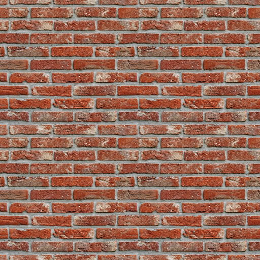
4.1 - Environment Mapping
First, I added the ability to load and store a texture to utils class as a SDL_Surface. RGB values of the texture can be accessed by indexing into the SDL_Surface pixel buffer.
class Material {
    vec3 color;
    float k_ambient;
    float k_diffuse;
    float k_specular;
    int shininess;
    SDL_Surface *texture;
public:
    bool LoadTexture(const char* path);
    vec3 GetTexture(vec3 sphere);
    ...
}
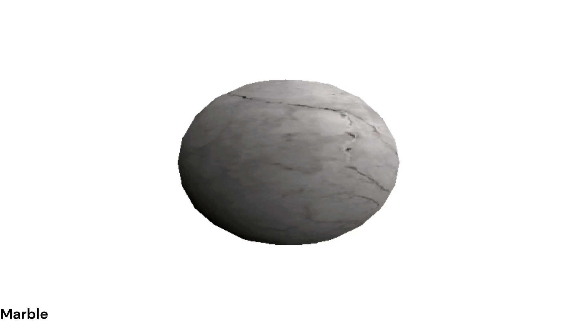
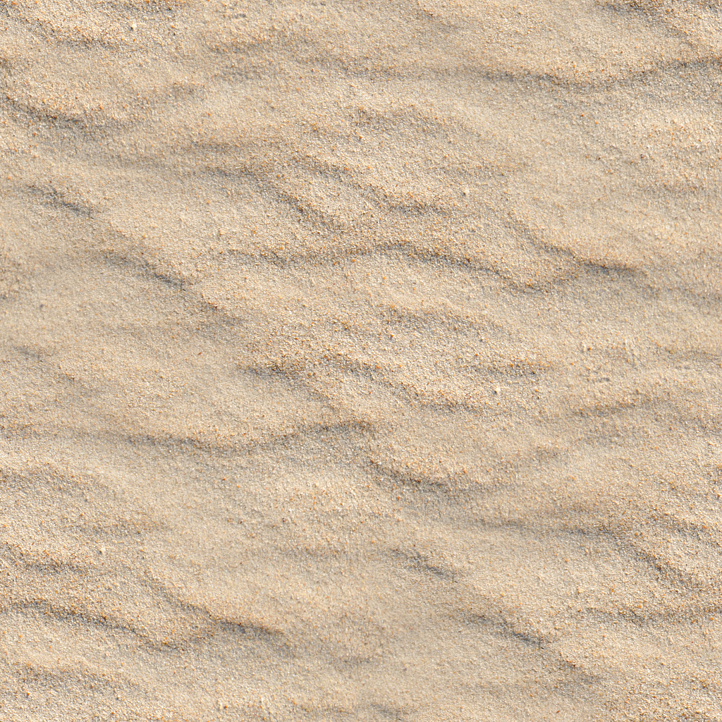
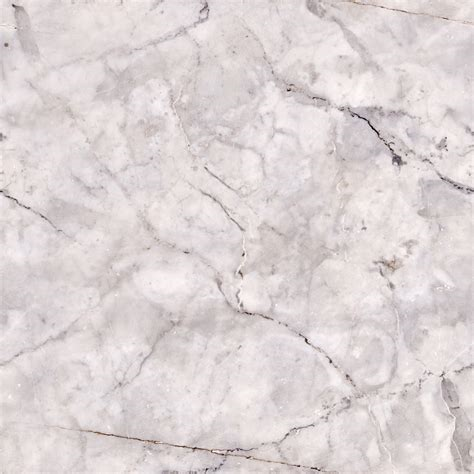
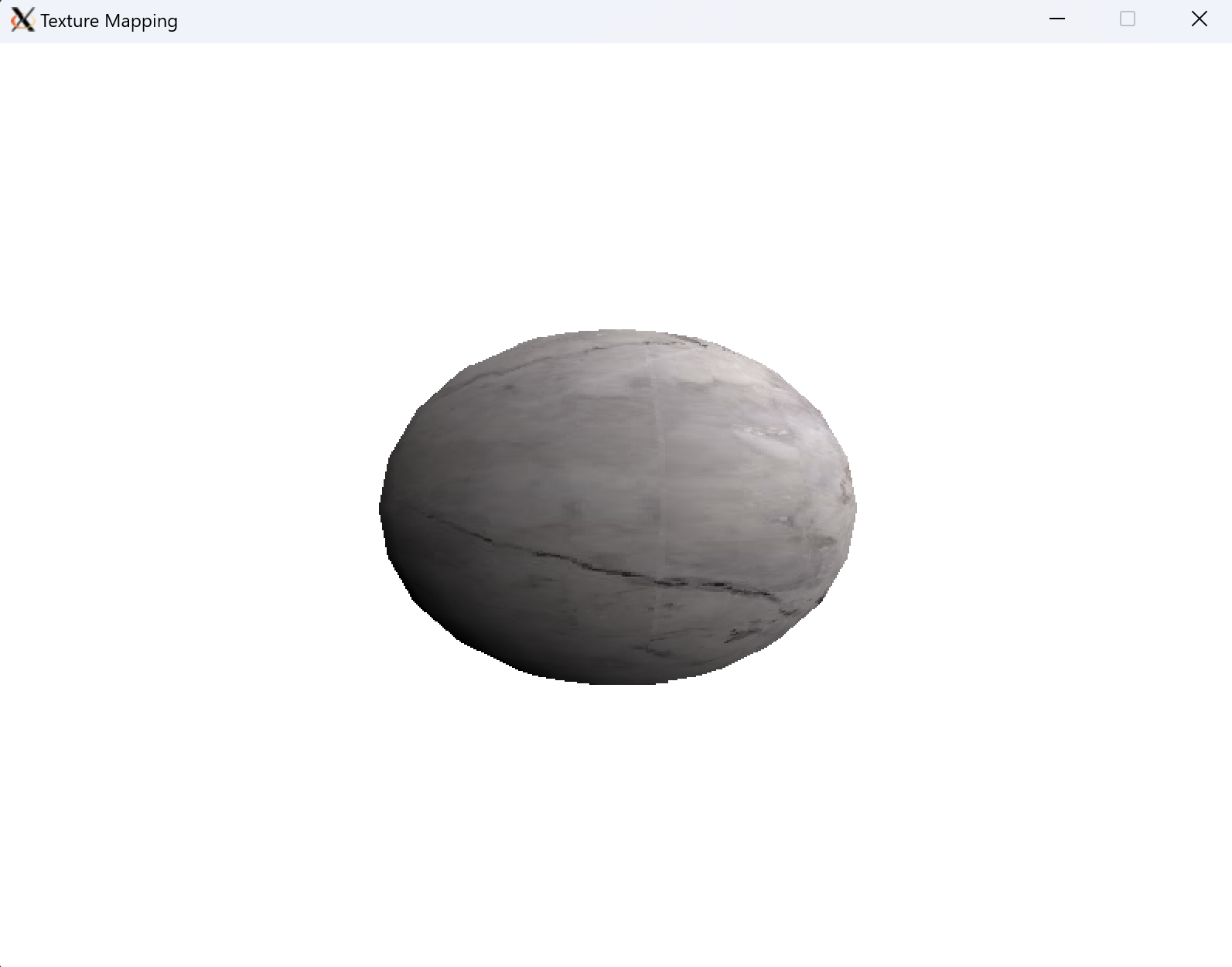
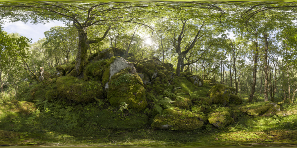
Then I implemented two stage texture mapping from object space to a sphere and then to the texture space. The GetTexture() function takes as input a unit vector, which corresponds to a point on a sphere. Then the latitude and longitude for that point are calculated, and scaled to x and y coordinates within the texture space. There is distortion in how the texture is projected on the sphere. The texture will look smushed at the poles, and in order to correct for this the spherically warped textures were used.
vec3 Material::GetTexture(vec3 sphere) {
    // Return a vec3 corresponding to rgb intensity 0 to 1

    // Map normal into latitude longitude
    float longitude = 0.5 - atan2(sphere.z, sphere.x) / (2.0 * M_PI);
    float latitude = 0.5 + asin(sphere.y) / M_PI;

    // Scale to integer between texture width and height
    int x = (int)round((this->texture->w - 1) * longitude);
    int y = (int)round((this->texture->h - 1) * latitude);

    Uint8 _r, _g, _b, _a;
    GetPixel(this->texture, x, y, &_r, &_g, &_b, &_a);

    return vec3(r, g, b);
}
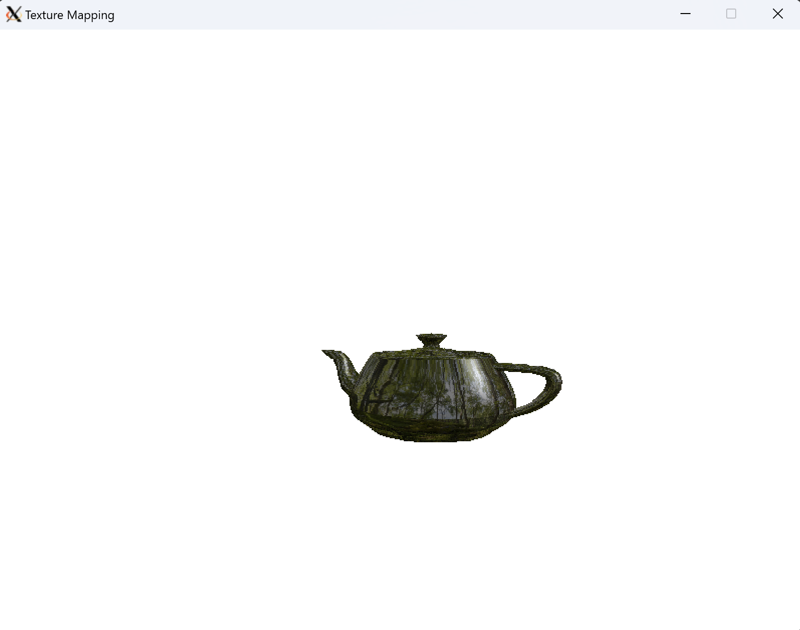
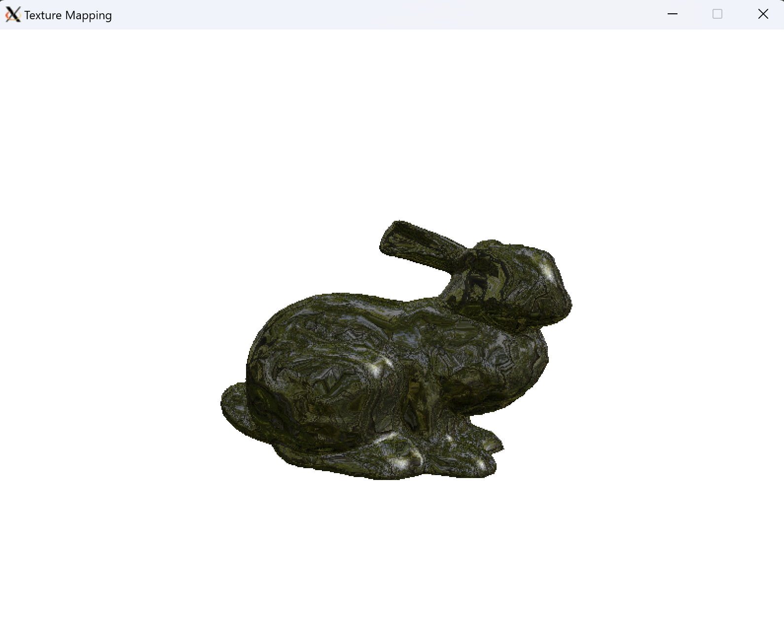
Environment mapping was implemented in utils/model.cpp:DrawEnvironment(). It was a relatively small change to the DrawPhong() function because I could reuse the normal map calculated during Phong shading as the input to GetTexture(). Then in the scan conversion process, I used the texture value as the color input into the Phong illumination model to get each pixel’s final intensity.
4.2 - Texture Mapping
I implemented Texture Mapping in utils/model.cpp:DrawTexture(). The challenge I had was making sure the texture was fixed to the local reference frame of the model. For example if the model is rotating, the texture also has to rotate with the model. Therefore, the mapping I chose was the vertex direction of each point in the model relative to the center of the model. This is all in the model’s local reference frame and is therefore precalculated when the model was loaded. Then I had to add another vector to the Edge class to support tri-linearly interpolating the vertex value. Finally the vertex value is normalized, texture value is calculated, and the Phong illumination model is invoked.
4.3 - Final Results
5 - References
- Lazy Foo’ Productions - SDL tutorials
- Learn WebGL
- OpenGL Programming Guide